
- Home
- Products
- Hot
- About Us
- Services
- Industry
- Contact
Views: 0 Author: Site Editor Publish Time: 2026-09-02 Origin: Site


Inconsistent assist gas pressure hides serious production costs on the shop floor. It directly causes increased dross, ruins precision parts, and accelerates wear on your expensive protective lenses. Manufacturers often obsess over increasing laser wattage to boost speed. However, they frequently overlook the true production bottleneck. The reliability of the air assist system actually dictates your overall cutting efficiency. A weak pneumatic setup completely wastes the potential of expensive fiber lasers.
This guide breaks down exactly how to evaluate your facility's pressure stability requirements. We will explore how to properly size your compressor components for peak performance. You will also learn proven methods to eliminate costly fluctuations from your air lines. Flawless cuts require a solid, stable pneumatic foundation. Read on to transform your gas delivery architecture and maximize machine uptime.
Minor pressure drops at the nozzle alter the entire melt-ejection dynamic. The assist gas acts as a physical tool to clear molten metal. When pressure dips, the gas fails to push the molten material through the kerf completely. This failure creates heavy bottom dross, deep striations, and jagged burrs on the workpiece. Operators must then perform manual grinding to salvage the parts. Manual rework destroys your production timeline. It turns a rapid automated process into a slow, labor-intensive bottleneck.
Piercing thick materials creates a harsh mechanical reality. The piercing phase demands a sudden, high-volume burst of air to break through the metal plate. The compressor system must deliver this massive volume instantly. If you experience unexpected laser cutting pressure fluctuation during this initial burst, the transition fails. The machine cannot transition smoothly into the continuous cut. The laser head will drag, causing cut failure right at the starting point. This wastes raw material and forces operators to restart the program.
Pressure instability also exponentially increases consumable contamination risks. The assist gas normally creates a protective downward barrier. When the pressure dips unexpectedly, this protective barrier weakens. Molten metal spatter can easily blow backward into the cutting head. This hot spatter lands directly on the nozzle and the protective glass. Lenses become pitted and clouded almost instantly. Frequent lens replacements drain your operating budget and force unnecessary machine downtime.
Different materials demand vastly different assist gas setups. Carbon steel generally operates under lower pressure requirements. Operators often rely on oxygen to create an exothermic reaction for cutting thick mild steel. However, many shops transition to compressed air for specific thin carbon steel applications to save on gas costs. The pressure remains relatively moderate in these cases.
Stainless steel and aluminum behave completely differently. These materials possess high viscosity when melted. They demand a continuous high-pressure air supply to blow away the stubborn molten material. Operators routinely set pressures between 200 and 250 PSI for these alloys. Without extreme pressure, the molten aluminum or stainless steel simply fuses back together behind the laser beam.
| Material Type | Primary Assist Gas | Typical Pressure Range (PSI) | Flow Demand Characteristics |
|---|---|---|---|
| Carbon Steel (Thick) | Oxygen | 10 - 80 PSI | Low volume, steady flow |
| Carbon Steel (Thin) | Compressed Air | 100 - 150 PSI | Moderate volume, continuous |
| Stainless Steel | Air / Nitrogen | 200 - 300+ PSI | High volume, extreme peak load |
| Aluminum | Air / Nitrogen | 200 - 250+ PSI | High volume, rapid clearing needed |
You must clearly differentiate between pressure (PSI) and volumetric flow (CFM). Pressure represents the force of the air. Volumetric flow represents the sheer amount of air available. Evaluating a compressor purely on its maximum PSI is a deeply flawed decision framework. A compressor might easily reach 250 PSI in a closed tank. However, if it cannot sustain the required CFM once the laser valve opens, the PSI will plummet immediately. High pressure means nothing without adequate volume to back it up.
Upgrading your equipment alters your baseline gas demands drastically. Moving from a 3kW fiber laser to a 12kW or 20kW system changes everything. Higher wattage lasers cut much faster and require wider nozzle diameters. A wider nozzle lets exponentially more air escape per second. Upgrading your laser wattage requires proportional upgrades in your air delivery capability. You cannot pair a massive 15kW laser with a legacy compressor meant for a 3kW machine.
The compressor unit should never feed the laser directly. Direct feeding guarantees catastrophic pressure drops during operation. Instead, you must install an air receiver tank between the compressor and the machine. The tank acts as the crucial buffer in your pneumatic architecture. It stores compressed air and absorbs the sudden volumetric demands of the cutting head. The tank provides the instant burst of air required for piercing thick plates.
Calculating the correct compressor buffer capacity prevents workflow interruptions. You must size the high-pressure storage tank strategically. Follow these standard sizing considerations:
Piping architecture introduces hidden risks to your system. Many facilities install appropriately sized compressors and tanks but fail on the delivery plumbing. Using undersized piping between the tank and the laser creates a severe pressure bottleneck. The tank might hold perfect pressure, but the air cannot travel fast enough through tiny hoses. Friction inside narrow pipes reduces the dynamic pressure reaching the nozzle. Always oversize your delivery piping to minimize friction loss and guarantee fast air delivery.
High-pressure compression generates intense heat and significant moisture. The physical act of squeezing ambient air concentrates atmospheric humidity into liquid water. Standard shop air systems routinely fail laser cutting standards because they ignore this condensation. If liquid water reaches your cutting head, it flashes into steam upon hitting the laser beam. This ruins the cut edge immediately.
You must evaluate your system against objective filtration standards. The laser industry typically demands ISO 8573-1 Class 1.4.1 compliance. This strict framework dictates maximum allowable levels for solid particulates, water vapor, and oil vapor. Maintaining rigorous cutting gas quality prevents thermal lensing. Thermal lensing occurs when oil or water droplets coat the protective glass, absorbing laser energy and shifting the focal point.
Dryer selection separates average setups from precision installations. Standard refrigerated dryers cool the air to drop out moisture. They typically reduce the pressure dew point to around 38°F (3°C). This setup may suffice for basic, low-power cutting tasks. However, refrigerated dryers fall short for extreme high-pressure applications or precision aerospace parts.
You should specify a desiccant dryer when processing highly reflective materials or operating high-wattage lasers. The -40°F dew point guarantees absolutely zero lens fogging. Dry, clean air ensures stable beam delivery and extends the lifespan of expensive optical components.
Choosing between Fixed Speed and Variable Speed Drive (VSD) technology impacts your daily operations. Fixed speed compressors run at maximum RPM continuously until the tank fills, then they shut off. VSD compressors adjust their motor speed dynamically to match the real-time air demand. You should evaluate VSD technology for facilities with fluctuating production schedules. They provide significant energy savings during partial load shifts. However, VSD units require a higher initial capital expenditure compared to traditional fixed-speed models.
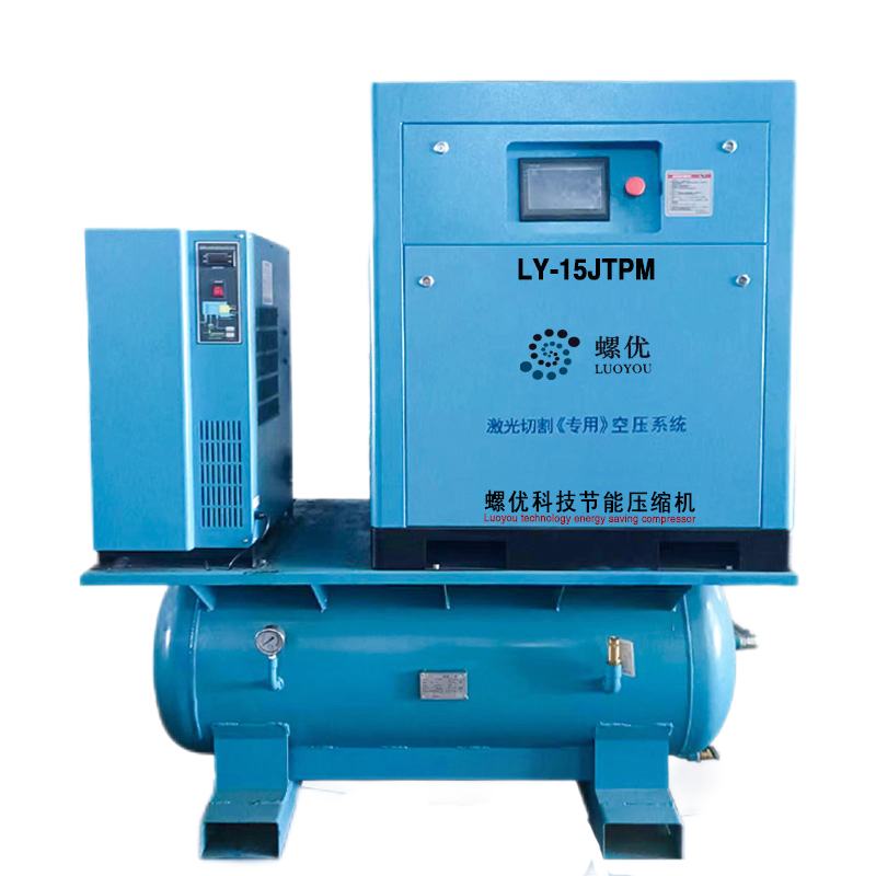
Implementation realities vary between packaged solutions and modular builds. Many vendors offer all-in-one skid solutions. These packaged skids combine the compressor, receiver tank, dryer, and filters onto a single metal base. They minimize installation time and reduce footprint. Conversely, building a custom modular system allows you to position the tank closer to the laser while keeping the noisy compressor in a separate room. Modular builds offer better customization for specialized piping layouts.
Verification and testing protocols protect your investment before final sign-off. Do not accept static pressure readings as proof of performance. You must advise buyers to request comprehensive data logging. Instruct the vendor to log laser cutting compressor pressure stability under simulated peak loads. Run a test program that mimics continuous piercing of thick stainless steel. Ensure the vendor guarantees dynamic pressure stability at the nozzle, not just static pressure at the compressor tank.
A: Typically, operators accept no more than a 5% fluctuation from the set cutting pressure. High-wattage systems cutting thick stainless steel may require even tighter tolerances. Maintaining strict pressure limits ensures the melt-ejection process remains constant, preventing burrs and edge striations during long production runs.
A: Rarely. Standard shop air usually operates at 90-120 PSI. This is entirely insufficient for high-pressure air assist, which often requires 230+ PSI. Furthermore, shop air systems almost always lack the rigorous desiccant filtration required to protect sensitive laser optics from water and oil contamination.
A: This indicates insufficient compressor buffer capacity or restricted delivery piping. The initial pierce draws a massive, sudden volume of air. Without an adequately sized receiver tank placed near the machine, the compressor simply cannot react fast enough to fill the void, causing an immediate pressure crash.


