
- Home
- Products
- Hot
- About Us
- Services
- Industry
- Contact
Views: 0 Author: Site Editor Publish Time: 2026-08-28 Origin: Site


Few things frustrate facility maintenance teams more than a struggling variable-speed compressor. You walk into the utility room and hear the motor spinning rapidly under load. However, the system pressure plateaus well below your target threshold. This specific scenario disrupts daily operations and causes widespread production downtime across the manufacturing floor. Furthermore, continuous high-speed operation wastes enormous amounts of electrical energy while failing to satisfy plant demand. Internal components also suffer from premature wear due to unrelenting mechanical stress.
Fortunately, this behavior rarely signals a catastrophic air-end failure. By applying a systematic diagnostic approach, you can uncover the true root cause quickly. In this guide, we explore how to isolate control anomalies, mechanical restrictions, and system-wide demand issues. You will learn actionable steps to prevent misdiagnosis and avoid unnecessary parts replacement. Ultimately, these strategies help you restore optimal performance to your equipment safely.
Before taking any physical machinery apart, we must establish a diagnostic baseline. You should begin your troubleshooting process at the digital controller. The Human-Machine Interface (HMI) holds vital operational clues. Operators frequently misinterpret these digital clues, leading them toward incorrect repair paths.
Always cross-reference the programmed compressor setpoint with the live discharge pressure reading. Sometimes, secondary pressure schedules actively override the primary target. Weekend shifts or unauthorized manual tweaks often change these parameters without documentation. You must confirm the actual target matches your intended pneumatic needs. A simple parameter correction often resolves the issue instantly.
You need to observe how the motor behaves during the active fault. We classify these behaviors into two distinct scenarios.
Scenario A: The motor runs at maximum RPM continuously. However, the pressure stagnates and refuses to climb. This behavior points directly toward system demand exceeding supply. It also suggests a severe mechanical restriction in the air flow path.
Scenario B: The motor ramps down unexpectedly. It might hover at mid-RPM before reaching the established target. This usually indicates a sensor failure, sluggish PID loop issues, or specific drive limits. Diagnosing a true VSD air compressor pressure fault depends heavily on which scenario you observe.
You must mandate Lockout/Tagout (LOTO) protocols immediately following digital diagnostics. Ensure complete system depressurization before moving past the HMI to physical inspections. Industrial safety standards dictate zero stored energy before technicians handle any internal components. Never bypass safety interlocks to speed up your troubleshooting workflow.
Digital components often trick physical machinery into behaving incorrectly. Sensors degrade over time and begin transmitting highly inaccurate signals. You must rule out software confusion before tearing down mechanical assemblies.
A drifting pressure transducer causes significant operational headaches. It sends falsely high 4-20mA electrical signals directly to the PLC. This bad data tricks the inverter into thinking it reached the target pressure. Consequently, the drive slows the motor prematurely to save energy.
We highly recommend testing the transducer directly. Install a calibrated external analog pressure gauge next to the sensor block. Compare the physical dial reading against the digital HMI screen during operation. If they differ significantly, you likely face a hidden pressure sensor fault. Replacing this inexpensive transducer typically restores full functionality.
Common Mistake: Technicians often adjust mechanical valves blindly without verifying transducer voltage. Always trust an independent analog gauge over an uncalibrated digital display.
Sometimes, the inverter artificially limits its own power output to survive. Inverter thermal derating forces the drive to cap its maximum Hertz. This internal defense mechanism protects sensitive electronics from catastrophic overheating. A dirty cooling heat sink or high ambient room temperatures often trigger this response.
Check the programmed maximum frequency parameter inside the drive menus. A previous technician might have lowered it accidentally during a routine service. Such an error creates an artificial VSD frequency limit. This permanently caps the machine's maximum CFM output regardless of plant demand.
The Proportional-Integral-Derivative (PID) loop controls motor acceleration rates. Sluggish PID settings cause the drive to react too slowly. If pressure drops suddenly, the motor fails to ramp up quickly enough. You may need a certified expert to adjust these complex sensitivity parameters. An incorrectly tuned proportional band creates severe pressure instability across the entire network.
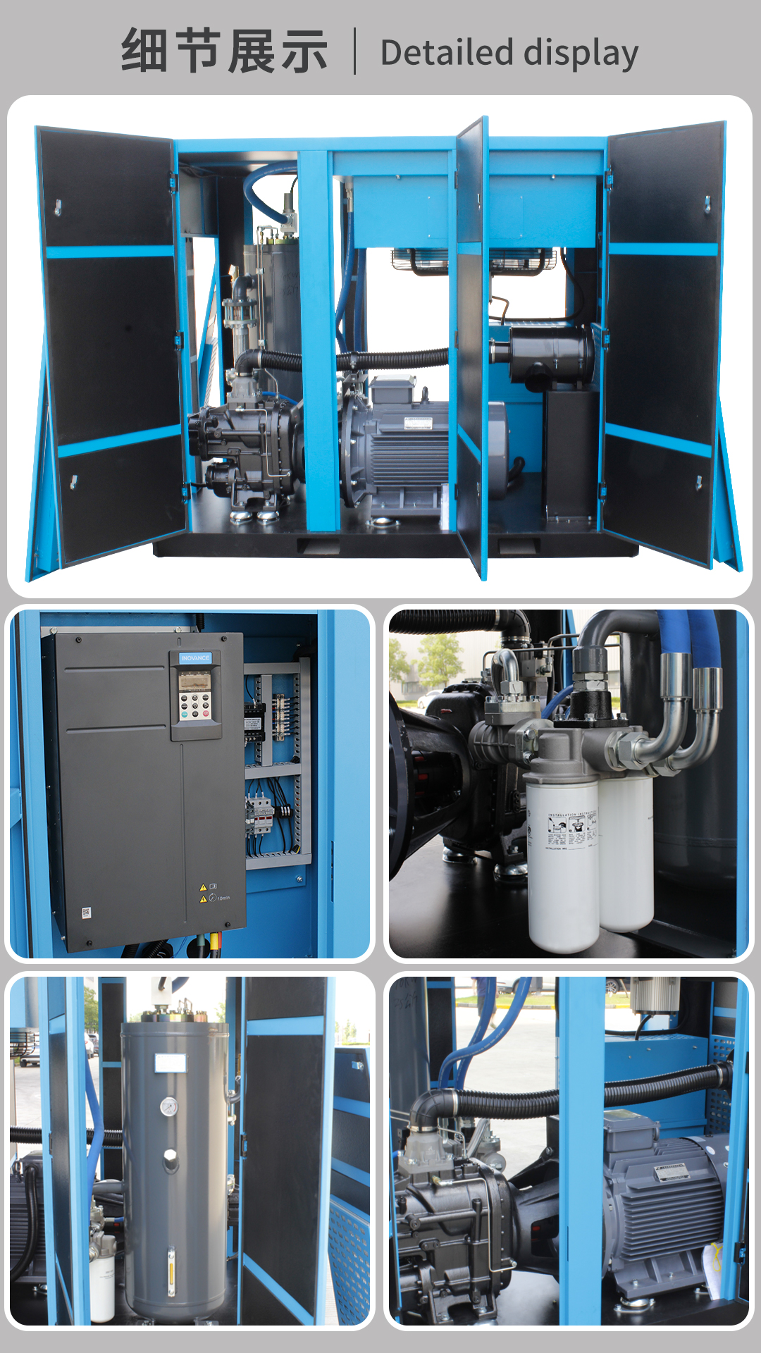
If software and sensors check out perfectly, you must inspect the hardware. Mechanical valves dictate exactly how air moves through the compression cycle. Physical blockages stop even the most powerful motors from building pressure.
The main intake valve controls incoming atmospheric air volume. A pneumatic cylinder or electric solenoid typically actuates this valve. If this actuator fails, the internal butterfly valve might stick partially closed. The air-end becomes starved of intake air immediately.
Under these conditions, reaching set pressure becomes mechanically impossible. The machine simply cannot compress air it does not possess. We recommend inspecting the small nylon control lines connecting to your intake unloader for tiny leaks.
The blowdown valve relieves internal sump pressure during normal machine shutdown. You should check if this specific valve remains stuck open. An open vent continuously dumps newly compressed air directly out to the atmosphere. The machine fights a losing battle trying to build network pressure.
Best Practice: Listen closely near the blowdown silencer while the machine runs under load. You should not hear any hissing air escaping during the active compression cycle.
Internal separators filter lubricating oil out of the compressed air stream. Over time, these dense fiberglass filters collapse or become heavily fouled with degraded oil. You will notice a very specific diagnostic symptom here. The internal sump pressure runs incredibly high, yet downstream network pressure remains critically low.
Operating under these restricted conditions poses a severe safety risk. Internal temperatures rise exponentially when flow stops. You must monitor differential pressure indicators very closely. Replace blocked separators immediately to avoid catastrophic thermal events or fires.
Table 1: Common Mechanical Restrictions and Associated Symptoms
| Mechanical Component | Failure Mode | Diagnostic Symptom |
|---|---|---|
| Intake Unloader Valve | Stuck closed / Actuator failed | Motor at 100% RPM, no pressure build, quiet air-end |
| Blowdown Valve | Stuck open / Leaking seal | Hissing sound at exhaust, slow pressure rise |
| Air/Oil Separator | Collapsed / Heavily fouled | High sump pressure, high temperature, low network pressure |
| Minimum Pressure Valve | Spring broken / Piston jammed | Unable to build internal oil circulation pressure initially |
Sometimes the compressor functions perfectly according to factory specifications. The actual problem originates downstream on the factory production floor. You must evaluate the broader environment before tearing into the equipment.
Before diagnosing internal hardware, audit your entire pneumatic network. Facilities frequently add new pneumatic machinery without recalculating their total air requirements. If your total plant CFM requirements exceed the unit's rated Free Air Delivery (FAD), pressure drops naturally. The unit will never reach the target threshold because physics prevents it.
This classic air demand overload requires adding supplementary compressor capacity. You cannot force a machine to push more air than its maximum physical rating.
Wasted air drains machine capacity just as quickly as new production equipment. Check the entire overhead pipeline for open bypass valves. Inspect all automatic drain traps located near filters and refrigerated dryers. Failed drain traps frequently stick in the open position, dumping massive volumes of air.
Also, look for ruptured downstream piping hidden out of sight. We recommend utilizing an ultrasonic leak detector during quiet weekend hours. You might discover that the unit produces its full rated capacity but loses it entirely to leaks.
Adequate storage volume stabilizes the entire production network. You should evaluate your primary receiver tank size carefully. A lack of adequate volume causes rapid and wild pressure volatility. The drive cannot physically track and compensate for these instantaneous swings.
Industry standards recommend installing three to five gallons of air storage per CFM of compressor capacity. Upgrading your receiver tank size often cures erratic system behavior instantly.
Maintenance teams need a clear, actionable path forward during emergencies. Use this structured checklist to guide your diagnostic journey systematically. Splitting tasks by complexity saves both time and maintenance budgets.
You can perform several non-invasive checks safely using in-house personnel. We strongly recommend starting here before spending money on external labor.
Some diagnostic tasks require specialized software tools and deep electrical expertise. Escalate the issue to professionals if you face these complex challenges.
Always evaluate the true financial cost of continued production downtime. Compare this against the cost of an expedited service call from the manufacturer. If you isolate the fault to the inverter drive itself, stop immediately. Specialized diagnostic software is usually required to proceed safely. Bring in a professional to prevent permanent electrical damage to the drive components.
Failing to reach set pressure remains a visible symptom rather than a specific disease. Systematic isolation provides the only reliable way to find the root cause accurately. We must transition carefully from digital parameters to physical valves and finally to overall plant demand.
Start your investigation with the easiest, non-invasive checks first. Verify HMI targets and perform basic sensor calibrations before grabbing any wrenches. Never dismantle complex mechanical components without ruling out software limits first. Finally, always contact a certified service provider if you suspect internal electrical faults. Proper systematic diagnostics save valuable time, preserve expensive equipment, and protect your operational bottom line.
A: This behavior usually indicates an air demand overload. Your plant is currently using more air than the machine can manufacture. Alternatively, you might have a massive downstream pipe leak wasting capacity. A mechanical intake restriction, like a stuck inlet valve, can also starve the machine of necessary air.
A: You should install a calibrated analog pressure gauge in parallel with the transducer. Observe both readings simultaneously during operation. If the analog gauge reads 90 PSI but the digital HMI falsely reads 110 PSI, the drive will slow down prematurely. This discrepancy confirms the sensor is faulty and requires replacement.
A: Yes. Extreme heat severely impacts electronic components. It can cause the inverter to initiate a VSD frequency limit to prevent catastrophic overheating. This safety mechanism artificially caps the motor's maximum speed. Consequently, it reduces total air output and prevents the system from reaching its target threshold.


