
- Home
- Products
- Hot
- About Us
- Services
- Industry
- Contact
Views: 0 Author: Site Editor Publish Time: 2026-09-27 Origin: Site


Sizing compressed air systems incorrectly carries massive financial and operational stakes for any modern manufacturing facility. Undersizing triggers severe pressure drops and crippling production bottlenecks right on the plant floor. Conversely, oversizing guarantees wasted energy and premature equipment failure resulting from constant short-cycling.
Decision-makers frequently confuse theoretical compressor displacement with actual delivered air in real-world conditions. You must understand this critical technical distinction to avoid incredibly costly system sizing errors. Misunderstanding these basic metrics leaves facilities struggling to maintain adequate pneumatic pressure at the actual tool level.
We will explore a highly standardized engineering framework to audit your facility demand accurately. You will learn to evaluate different modern compressor technologies and specify the exact configuration you need. This comprehensive guide provides actionable steps to achieve optimal system performance and maximize your initial capital investment return.
Many plant managers buy bigger equipment simply to create perceived safety margins. This well-intentioned approach actually creates severe operational penalties. We call this common error the oversizing trap. Oversized compressors reach their set target pressure much too quickly. They then immediately switch to an unloaded state. An unloaded compressor produces absolutely zero usable air for your factory. However, it still continually draws 30% to 40% of its full electrical motor load. You pay heavy utility premiums for idle electricity. Constant start-stop cycles also wear out motor bearings and intake valves prematurely.
On the flip side, undersizing creates immediate chaos across your production lines. Facilities experience dangerous pressure drops during peak shift hours. Pneumatic tools begin operating far below manufacturer specifications. Quality control failures spike instantly when air pressure fluctuates. For example, pneumatic torque wrenches fail to tighten heavy bolts correctly. Automated paint sprayers deliver uneven coats. You ultimately end up scrapping highly expensive finished products.
You must base all equipment evaluations strictly on actual Free Air Delivery (FAD). Many uneducated buyers look at theoretical swept volume instead. Swept volume only measures raw cylinder geometry multiplied by rotational speed. It completely ignores internal slip, heat expansion, and mechanical friction losses. FAD measures the exact volumetric flow of usable air exiting the final discharge valve. Relying solely on motor horsepower remains equally dangerous. Two different 50HP motors can produce vastly different FAD volumes depending on their internal air-end efficiencies.
You must start your assessment by aggregating all end-use air requirements. Plant engineers should physically inventory every single pneumatic tool. Document all compressed air equipment utilized across the entire facility.
You cannot simply guess these foundational numbers. Use documented spec sheets to establish accurate baseline data. Guesswork at this stage compromises the entire sizing process.
Table 1: Pneumatic Tool Inventory and Demand Logging Example
| Equipment Type | Required Pressure (PSI) | Max Consumption (CFM) | Quantity in Plant | Total Max CFM |
|---|---|---|---|---|
| Impact Wrenches | 90 | 35 | 4 | 140 |
| Paint Booth Sprayers | 100 | 50 | 2 | 100 |
| Pneumatic Clamps | 85 | 15 | 10 | 150 |
| Abrasive Blaster | 110 | 120 | 1 | 120 |
You must apply the correct load factor next. We commonly refer to this metric as the duty cycle. Seldom do all factory machines operate simultaneously at their maximum capacity. You must establish realistic simultaneous usage rates.
A heavy grinding tool might run continuously during an entire shift. A small pneumatic clamp might actuate once every five minutes. Calculate a time-weighted average demand across your typical production shift. Compare this calculated average against your absolute peak demand spikes. This dual calculation approach prevents you from sizing the main compressor solely for a rare one-second consumption peak.
Finally, you must account for inevitable system inefficiencies. No industrial piping network remains perfectly sealed over time. You must factor in an evidence-based leakage allowance into your calculations. The accepted industry standard typically ranges from 10% to 20%.
Older steel distribution pipes often leak much more than modern aluminum networks. Additionally, always add a conservative capacity buffer for planned short-term facility expansions. You do this to avoid immediate equipment obsolescence when you add a new production line next year.
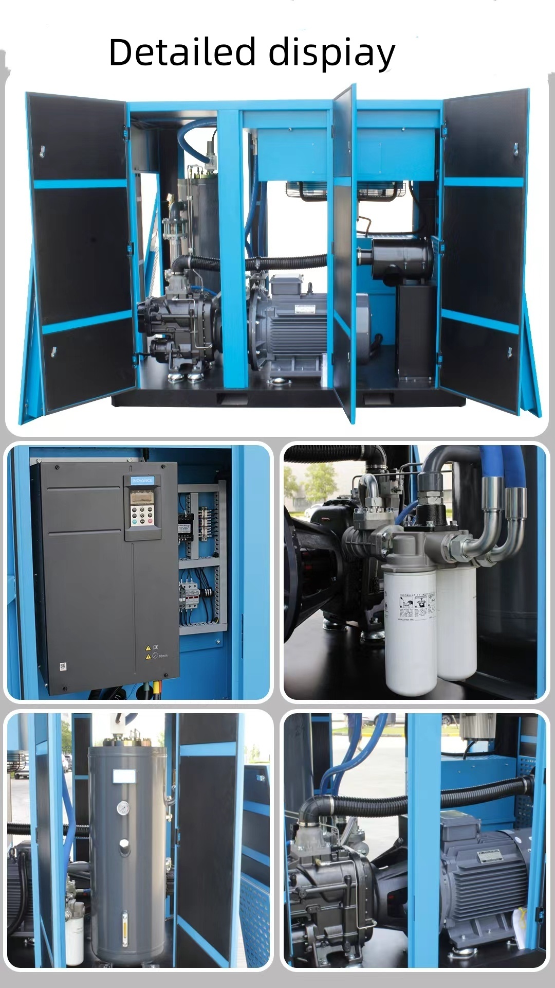
Evaluate fixed-speed models rigorously for highly stable plant operations. Facilities running 24/7 steady manufacturing require constant, non-varying air volumes. Fixed-speed units excel specifically in these continuous environments. They provide a distinct CapEx advantage over more complex variable options.
Their inherent mechanical simplicity makes routine maintenance highly straightforward. If your factory floor consumes a constant 500 CFM all day without dropping, a properly sized fixed-speed compressor delivers optimal efficiency. You avoid paying extra for variable technology you simply do not need.
Fluctuating plant loads require vastly different engineering approaches. Analyze the integration of a 75kW permanent magnet screw compressor for facilities experiencing variable shift demands. These modern units adapt continuously to changing factory conditions.
Permanent magnet (PM) motors maintain remarkably high efficiency even at partial loads. They speed up or slow down exactly matching real-time plant requirements. This eliminates the severe energy waste associated with unloaded idle times. Evaluate the ROI carefully here. The initial capital expenditure for PM units runs higher. However, you recover this premium rapidly through drastically reduced electricity bills. If your existing equipment runs unloaded more than 20% of the time, this technology easily justifies its higher purchase price.
Do not ignore ambient environmental conditions in your facility. They severely alter actual machine performance. Hotter intake air acts significantly less dense than cold air. Less dense air means the compressor ingests less physical oxygen mass per revolution. This directly reduces the actual mass of air compressed. A hot, poorly ventilated compressor room essentially starves the air-end.
Elevation plays an equally critical role in capacity planning. Higher altitudes inherently possess lower atmospheric pressure. This thinner air directly reduces effective screw compressor free air delivery by limiting the initial intake mass. A machine rated for 300 CFM at sea level might only deliver 260 CFM in Denver. Always apply manufacturer derating formulas based on your exact geographical altitude.
Downstream infrastructure dependencies heavily dictate overall system success. Matching your required FAD demands adequate receiver tank sizing. A large receiver tank stores pneumatic energy. It handles sudden peak demand spikes effortlessly. This prevents the primary compressor from triggering a rapid start/stop cycle.
Furthermore, you must evaluate your existing piping network diameter constraints. Small pipes create excessive internal friction. Friction causes massive pressure drops downstream. Narrow pipes can artificially restrict air delivery despite having perfectly sized compressor equipment upstream. We see this common mistake frequently in older factories. Even highly robust screw compressor free air delivery cannot overcome highly restrictive half-inch distribution lines.
Evaluating OEM proposals requires strict engineering discipline. You must mandate ISO 1217 Annex C compliance on all incoming vendor quotes. This specific testing standard guarantees highly accurate performance data. It ensures you conduct a true apples-to-apples FAD comparison. Vendors dodging this specific standard often inflate their capacity numbers artificially.
Evaluate the Specific Power metric next. We express this metric as kW/100 CFM. Specific power measures exactly how much electricity generates a specific volume of air. Shift your entire procurement focus away from upfront sticker prices. Focus instead on lifetime operating efficiency. A cheaper compressor displaying poor specific power consumes thousands of extra dollars in utility costs annually.
Chart 1: Vendor Proposal Evaluation Matrix
| Evaluation Criteria | Why It Matters | What to Demand from Vendor |
|---|---|---|
| ISO 1217 Annex C FAD | Ensures actual usable air volume matching | Certified test data sheet for the exact model |
| Specific Power (kW/100 CFM) | Determines lifetime electricity expenses | Guaranteed specific power at full and partial loads |
| Control System Capabilities | Prevents unloaded running waste | Details on VSD integration and staging logic |
| Air End Warranty | Protects against catastrophic failure | Minimum 5-year coverage on main rotary components |
Scrutinize air end warranties and scheduled service intervals closely. Assess the manufacturer’s projected maintenance schedule. Review the expected overhaul timelines for your specific load profile. Some vendors require wildly expensive synthetic oils to maintain warranty status. Others mandate frequent bearing replacements. Calculate these lifetime service requirements before you sign any final purchase order.
Matching capacity to demand remains a strict engineering calculation. It is never a guessing game. Sizing requires empirical data, patience, and realistic factory usage assessments. You must prioritize actual Free Air Delivery over theoretical metrics. Furthermore, always evaluate your specific shift patterns to decide between fixed-speed and variable-speed technologies.
We highly recommend initiating a professional air demand audit immediately. Use digital data loggers and precise flow meters on your existing system. Gather empirical baseline data for a full week. Only after reviewing this data should you issue an RFQ for new manufacturing equipment.
A: CFM measures air flow at current conditions. SCFM standardizes this measurement to specific baseline conditions (typically 68°F, 0% humidity, and sea-level pressure). FAD measures the actual usable air delivered at the discharge valve under your specific operating conditions, accounting for all mechanical and environmental losses.
A: The general rule requires 1 to 3 gallons of storage per CFM of compressor capacity. Fixed-speed units typically need 3 gallons per CFM to prevent rapid cycling. Variable speed compressors adapt better to demand changes, often requiring only 1 to 2 gallons per CFM.
A: Yes, PM motors can technically handle continuous full loads. However, running them constantly at maximum RPM completely negates their variable-speed energy efficiency benefits. If your plant demands 100% load 24/7, a fixed-speed compressor provides a much better return on investment.


