
- Home
- Products
- Hot
- About Us
- Services
- Industry
- Contact
Views: 0 Author: Site Editor Publish Time: 2026-06-14 Origin: Site


In the demanding realm of industrial pneumatics, fluid management dictates your overall system reliability. Inside any oil-lubricated screw compressor, fluid performs three non-negotiable tasks. It cools the extreme heat of compression, seals the micro-clearances between rotating metal surfaces, and lubricates heavy-duty bearings. However, this essential fluid becomes a severe contaminant if allowed to exit the internal network. Allowing lubricant to reach downstream equipment ruins sensitive pneumatic tools, fouls precision instrumentation, and spoils expensive end products.
You must frame the air-oil separation phase as a critical operational safeguard rather than a simple consumable maintenance item. This single component heavily influences your energy efficiency, equipment longevity, and daily maintenance overhead. This article provides a comprehensive technical evaluation framework. We aim to help you select and maintain these components flawlessly. You will learn how to achieve strict oil carryover control and maximize your equipment's lifecycle profitability without compromising safety.
Operating a compressed air system efficiently demands rigorous contamination control. Excess fluid escaping the main shell creates a massive ripple effect across your entire manufacturing facility.
When an air oil separator fails, lubricant floods the downstream network. This contamination damages delicate pneumatic cylinders and solenoid valves almost immediately. Furthermore, it permanently fouls the desiccants inside air dryers. Once oil coats a desiccant bed, the chemical beads lose their moisture-absorbing properties entirely. This failure leads to wet, oily air traveling through your pipes. Ultimately, this degrades final product quality, causing catastrophic rejections in industries like food packaging, pharmaceutical manufacturing, electronics assembly, or automotive spray painting.
Filtration efficiency shares an inverse relationship with energy consumption. Forcing compressed air through saturated or sub-optimal media continuously increases the pressure differential. A clogged element creates a severe internal bottleneck. The electric motor must work significantly harder to overcome this resistance and maintain your desired plant pressure.
Industry standards reveal a harsh reality regarding restricted airflow. An increase of just 2 PSIG across a clogged vessel increases overall energy consumption by roughly 1%. Consider a standard 100-horsepower rotary system running continuously for 8,000 hours a year. That minor 1% energy penalty translates directly into thousands of wasted kilowatt-hours. Over a year of operation, this pressure penalty inflates your utility costs dramatically. Changing the filter element on a strict schedule prevents this invisible financial drain.
Uncaptured lubricant translates directly into frequent, expensive top-offs. Premium synthetic lubricants, such as Polyalphaolefins (PAO) or Polyalkylene Glycols (PAG), represent a major maintenance expense. You bleed money rapidly when these high-grade fluids blow past the separation vessel into the factory lines. Beyond the direct purchasing cost, you also incur strict environmental disposal fees for cleaning up oily condensate downstream.
Maintaining high separation efficiency reclaims these valuable fluids. A premium compressor oil separator captures the mist and routes it securely back into the internal cooling loop. This vital recovery process keeps your fluid purchasing and disposal budgets strictly under control.
Understanding how the system strips oil from high-velocity air helps you troubleshoot issues faster. It utilizes a highly effective, multi-stage physical process to isolate the fluids.
Mechanical separation handles the bulk of the fluid recovery. It relies on fundamental physics to drop heavy liquids out of the fast-moving air stream.
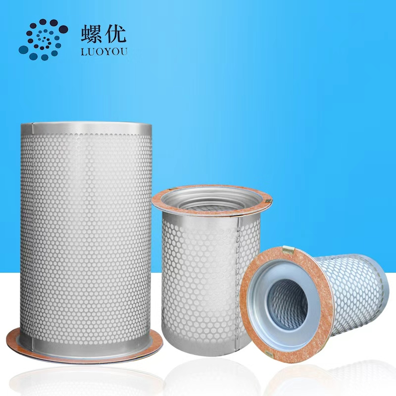
Mechanical forces cannot capture microscopic mists suspended in the air. These tiny aerosols must pass through an air oil separator element for final polishing. This stage uses specialized media, typically spun fiberglass or advanced synthetic polymer fibers arranged in deep wraps.
Coalescing Filtration: The compressed air normally flows from the outside of the filter element to the inside. The oil mist navigates a complex, tortuous path through these tightly woven fibers. Through mechanisms like direct interception and inertial impaction, aerosols impact the fibers and bind together. They form larger, heavier droplets that eventually slip down to the bottom of the filter assembly, leaving clean, dry air to exit the system.
Separated fluid constantly pools at the bottom of the internal element. The scavenge line serves a vital function in continuous fluid recovery. It siphons this captured fluid from the bottom of the vessel back into the air end. A dedicated internal check valve prevents any reverse flow during shutdown. This continuous siphoning ensures reliable cooling and prevents the filter media from drowning in accumulated fluid.
Choosing the correct replacement component requires objective technical metrics. You must evaluate multiple parameters to ensure maximum system reliability and airflow purity.
You must establish a strict performance benchmark for OCO. High-quality filter media should consistently deliver an OCO of less than 2 to 3 mg/m³ under full-load rated conditions. This metric translates to roughly 3 parts per million (ppm). Achieving this excellent baseline protects your downstream filtration processes from incremental contamination and extends the life of subsequent inline filters.
Premium units exhibit exceptionally low initial pressure drops. Specify models that sit around 0.3 Bar straight out of the box. Low resistance guarantees that energy efficiency remains optimized from day one. High starting resistance wastes motor power immediately and drastically shortens the viable lifespan of the filter element.
Compressor designs utilize different separation housings based on their Free Air Delivery (FAD) capacity. Consider these lifecycle differences when planning your preventative maintenance schedules:
| Evaluation Metric | Spin-on Separators | Drop-in / Cartridge Separators |
|---|---|---|
| Typical Application | Smaller industrial systems (lower FAD capacity) | Larger, high-demand industrial configurations |
| Maintenance Process | Simple, quick external canister replacement | Requires unbolting and removing the heavy housing lid |
| Average Functional Life | Around 4,000 operating hours | Extended lifecycles, often up to 8,000 hours or annually |
Ensure your chosen filter material remains chemically compatible with your specific fluid chemistry. Standard mineral oils behave very differently than aggressive synthetic lubricants. Structural adhesives and potting compounds used in the filter end-caps must handle synthetic oils without dissolving or swelling. If the adhesive degrades, the high-pressure air simply bypasses the filter media entirely, causing massive downstream flooding. Furthermore, the unit must be rated for maximum operating temperatures, which frequently reach up to 120 °C during heavy summer loads.
Many operators severely underestimate the violent physical forces at play inside a separation vessel. Understanding these internal hazards prevents catastrophic facility accidents.
The internal vessel environment features extreme high-velocity friction. Oil and compressed air violently pass through fine synthetic media continuously. This intense friction generates significant static electricity through a phenomenon known as the triboelectric effect. If left unmanaged, this massive static accumulation presents a severe fire hazard inside a highly pressurized, oxygen-rich environment.
Authentic, high-quality elements utilize robust built-in grounding components. Manufacturers embed specific metal staples, specialized conductive mesh layers, or conductive gaskets into the end caps. These crucial mechanical mechanisms route static charges safely away from the sensitive filter media. The electrical charge travels securely into the grounded compressor chassis, dissipating the danger harmlessly.
We strongly warn against using unverified, ultra-cheap aftermarket parts. Counterfeit filters routinely lack proper static dissipation features to save on manufacturing costs. This oversight creates a lethal risk. Static buildup can cause internal arcing between the ungrounded metal components. A single internal electrical spark can instantly ignite vaporized fluid mists. This chain reaction often leads to catastrophic receiver tank explosions. Never compromise facility safety for marginal upfront cost savings.
Consistent monitoring prevents unexpected mechanical failures. Implementing proactive diagnostic strategies keeps your equipment running smoothly and safely around the clock.
Advise your maintenance operators to actively monitor differential pressure gauges. Compressed air filtration efficiency degrades steadily over time as media clogs with particulates and oxidized oil. Establish a strict replacement protocol based on hard data rather than guesswork. You must replace the unit when the pressure drop approaches the manufacturer's critical threshold. This limit commonly sits around 10 PSIG over the clean installation baseline.
We regularly identify the scavenge line as the primary culprit for sudden carryover spikes. If this narrow internal line becomes blocked by metal dust, debris, or varnished fluid, disaster strikes quickly. The captured fluid cannot return to the system. Consequently, the separator element floods entirely within hours. Once heavily saturated, it becomes completely useless regardless of its physical age or condition. Always inspect the return line and clear its internal orifice first during any carryover troubleshooting event.
We argue strongly against pushing components past their rated hours to stretch maintenance budgets. The energy penalty of a clogged filter adds up incredibly fast, wiping out any perceived savings on parts. Furthermore, old and brittle media risks sudden structural collapse under pressure. If the media tears, massive amounts of fluid flood your factory lines instantly. The subsequent energy waste, production downtime, and risk of catastrophic collapse heavily outweigh the price of a fresh replacement filter.
The separation unit serves as the absolute decisive barrier in your air system. It actively stands between reliable internal lubrication and devastating downstream contamination. Protecting this barrier ensures the mechanical integrity of your entire production line and prevents costly pneumatic tool failures.
Emphasize comprehensive evaluation when making critical purchasing decisions. Focus on maintaining operational efficiency through predictably low pressure drops. Prioritize excellent fluid recovery via strict OCO rate limits. Most importantly, demand operational safety by verifying proper grounding mechanisms inside the filter structure. These engineering factors dictate true long-term value far beyond initial component pricing.
Take immediate action to secure your system's health. Audit your current pressure differential logs today to spot concerning trends. Verify your scavenge line functionality and clean the internal orifice during the next scheduled maintenance window. Proactive oversight guarantees safe, continuous, and highly efficient factory operations.
A: An air-oil separator operates inside the compressor to strip fluid from the compressed air before it exits the machine. Conversely, an oil-water separator operates downstream. It removes residual oils from the liquid condensate. This ensures the water is legally and safely discharged into local wastewater systems without causing environmental harm.
A: Watch for excessive fluid consumption and frequent top-offs. You might notice visible mist at the points of use. Degraded downstream filters and unusually high pressure-drop readings on the compressor controller also indicate failure. If you spot fluid pooling in the air lines or dryer inputs, inspect the separation element immediately.
A: Extreme heat degrades components quickly, but running too cold is equally damaging. Cold operation prevents moisture in the air from vaporizing. This creates condensation inside the fluid system, which emulsifies the internal oils. Emulsified mixtures prematurely blind and ruin the filter media. Maintaining the proper operating temperature is key.


