
- Home
- Products
- Hot
- About Us
- Services
- Industry
- Contact
Views: 0 Author: Site Editor Publish Time: 2026-08-23 Origin: Site


Pressure drop, commonly known as Delta P, is an unavoidable reality in any pneumatic or HVAC system. Some resistance naturally occurs as air moves through dense filter media. However, an unexpected spike signals deep systemic inefficiency. It often warns of impending equipment failure. Unmanaged compressed air filter pressure drop forces your compressors to work significantly harder. They must push past internal blockages just to maintain baseline airflow. This extra mechanical strain exponentially increases energy consumption. It also drastically inflates your daily operating expenses.
In this comprehensive guide, we objectively diagnose the root causes of abnormal pressure drops. You will learn how to evaluate the delicate balance between high filtration efficiency and low energy use. We also establish a highly practical, condition-based protocol for timely replacements. Mastering these concepts keeps your facility running smoothly and prevents costly, unexpected downtime.
The initial purchase price of a new filter element represents only a tiny fraction of its true cost. The real financial drain comes from the energy required to force air through a restricted passage over many months. Compressors consume vast amounts of electricity. When filters clog, energy demands soar. Facility managers often overlook this hidden expense. They focus on the upfront cost rather than the long-term energy penalty.
Equipment strain is another severe consequence. High differential pressure forces the compressor to increase its discharge pressure just to meet downstream demand. This excessive workload accelerates wear and tear on critical internal components. Bearings, motor windings, and airends all suffer. It heavily risks thermal overload. You should constantly monitor discharge temperatures to spot these dangerous trends early.
Downstream contamination poses an even greater risk to your production line. Filters have physical structural limits. Pushing a heavily loaded filter past its breaking point causes the media to rupture. Once the media tears, the compressed air simply bypasses the filtration stage entirely. This failure introduces harmful contaminants like rust, pipe scale, and oil aerosols into sensitive downstream pneumatic tools. It damages air cylinders, spoils automotive paint finishes, and ruins cleanroom environments.
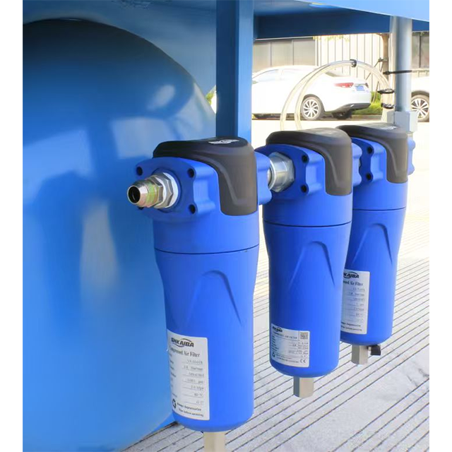
Diagnosing excessive restriction requires a structured approach. Several independent factors can trigger severe pressure drops. Understanding these root causes helps you implement lasting solutions.
Natural accumulation occurs in every industrial environment. Dust, dirt, and pipe scale build up steadily over time. This creates an exponential curve of airflow resistance. During the first few months, pressure drop increases slowly. As the outer pores clog, air forces its way through the remaining open pores. Air velocity through these narrow channels increases sharply. This suddenly accelerates the final blocking phase. You eventually end up with a severely blocked precision filter. Ignoring this exponential curve leads to sudden drops in downstream line pressure.
Many systems suffer from upstream equipment failures. Bulk liquid separators or refrigerated air dryers sometimes malfunction. When they fail, massive amounts of liquid carry over into the filtration housings. Liquid emulsion heavily blinds the filter media. It forms a thick physical barrier across the surface. This drastic reduction in open surface area prevents air from passing through. The restriction spikes almost immediately. Coalescing filters handle fine aerosols well, but bulk liquids will drown them instantly.
System demand must closely match the filter’s rated flow capacity (SCFM). Mismatches happen frequently during facility expansions. Engineers might upgrade the main compressor without upgrading the downstream housings. Pushing peak flow rates through an undersized housing creates instant problems. You see an immediate, artificial pressure drop. This restriction happens completely independent of any dirt loading. It simply means the physical pipe geometry is too restrictive for the volume of air.
You might deploy absolute or ultra-fine filters without a proper strategy. For example, using a 0.01-micron element directly after the compressor causes rapid blinding. The fine element attempts to capture large rust flakes and bulk oil. It clogs almost instantly. This forces constant replacement cycles. You must use a multi-stage approach. A general-purpose pre-filter must capture large debris before the air reaches the high-efficiency unit.
Common Mistake: Facility operators often skip pre-filtration stages to save space or initial capital. This shortcut directly causes rapid failure of ultra-fine elements. Always step down your micron ratings progressively.
Selecting the right equipment requires balancing air purity against electrical consumption. You cannot maximize both simultaneously without making strategic compromises. Understanding these trade-offs ensures efficient system design.
Higher filtration tiers require tighter media matrices. Stricter ISO 8573-1 purity classes demand exceptionally fine pores to trap sub-micron particles. This naturally results in a higher initial pressure drop. The "clean" or "wet" initial drops will always be higher for a Class 1 oil filter compared to a Class 4 general-purpose filter. You must accept this efficiency tax if your process requires ultra-clean air.
Modern pleated designs offer a distinct advantage over legacy technologies. Pleating the media massively increases the available surface area packed inside the same housing volume. This expanded surface area reduces the velocity of air moving through the pores. It mitigates pressure drops while maintaining high capture efficiency. Wrapped media relies on thick layers of material tightly wound together. It generally causes higher baseline restriction and holds less dirt overall.
Filtration Media Comparison
| Media Design | Surface Area | Dirt Holding Capacity | Initial Restriction | Best Application Use |
|---|---|---|---|---|
| Pleated Microglass | Very High | Excellent | Low to Moderate | High-flow industrial systems |
| Wrapped Depth Media | Low | Moderate | Moderate to High | Older legacy installations |
| Sintered Bronze | Moderate | Low | Very Low | Coarse pre-filtration |
Beware of deceptive marketing myths. A filter claiming "zero pressure drop" is misleading you. It either fails to capture microscopic contaminants, or it allows internal bypass around the seals. Our actual goal is optimized differential pressure, not zero. Zero restriction is physically impossible when forcing air through a physical barrier.
Knowing exactly when to swap your elements prevents both wasted money and unexpected downtime. A rigorous monitoring strategy serves as your best defense against system inefficiency.
Static 6-month or 12-month schedules have major flaws. If your facility runs minimal shifts, a 6-month swap forces you to discard perfectly good elements. Conversely, a 24/7 manufacturing plant might destroy an element in three months. Calendar schedules risk both under-utilization and over-saturation. Condition-based monitoring acts as a far superior alternative. Utilize visual pop-up indicators. Install mechanical differential pressure gauges. Deploy smart IoT pressure transducers. These diagnostic tools ensure highly accurate replacement timing based on actual restriction levels.
You must find the exact threshold where excess energy costs exceed the price of new parts. The electricity required to overcome resistance eventually outweighs a new element's price. In most pneumatic systems, this optimal change-out point sits around 6 to 10 PSID. Monitor local energy utility rates to refine this number for your specific plant. When you cross this threshold, initiate a filter element replacement immediately. Waiting longer simply burns through your operational budget.
Inspect your elements closely upon removal. Look for physical signs of crushing or media migration. Check for end-cap separation caused by heat degradation. Ensure the internal support cores remain rigid. Make this visual inspection a standard practice during all routine compressed air maintenance. Finding a crushed element indicates you waited much too long to swap it out. It also highlights potential surges in line pressure.
When upgrading your pneumatic infrastructure, you must scrutinize vendor claims. Making smart procurement choices upfront saves thousands of dollars in downstream electricity bills.
Demand empirical proof from your suppliers. Ask for independent, third-party tested data. ISO 12500 testing provides highly accurate "dry" and "wet" initial pressure drop metrics. Coalescing filters operate in a fully saturated state. Therefore, a "dry" pressure drop metric is useless for real-world calculations. Do not rely on unregulated marketing sheets. Request the official testing certificates.
Always oversize your filter housing slightly. Aim for 15-20% above your current peak volumetric demand. This simple step substantially lowers internal air velocity. Slower air improves particulate capture rates. It reduces differential pressure right out of the box. Oversizing also heavily extends the operational life of your element. A slightly larger initial housing investment pays massive dividends in long-term energy savings.
Match replacement elements perfectly to the housing. The internal O-rings and housing seals must align smoothly to prevent any air bypass. An improperly seated seal allows contaminated air to leak directly downstream. Additionally, ensure you meet specific industry compliance standards. Food-grade FDA compliance requires highly specific, non-toxic materials. Automotive paint environments need strictly regulated, silicone-free elements to prevent surface finish defects.
We must fundamentally shift our operational mindset. Stop viewing filters purely as a disposable maintenance expense. Start viewing them as an active energy management tool. Diagnosing the exact cause of high restriction dictates your next logical step. You might only need a simple element swap to restore optimal flow. Alternatively, you may uncover a need for a broader system sizing correction.
Take proactive steps today. Audit your current differential pressure gauges across the entire facility. Consult with a qualified applications engineer to establish an accurate baseline for your air purity and pressure loss metrics. Catching a restriction early saves your compressors from dangerous thermal overload and slashes your monthly utility bills.
A: Baseline metrics vary slightly by manufacturer and design. However, you can expect 1 to 2 PSI for standard coalescing filters. This number goes slightly higher when the media becomes fully wetted during normal operation. Always refer to manufacturer ISO testing data for exact baseline expectations.
A: You should install pressure gauges both upstream and downstream of the filter housing. Subtracting the downstream reading from the upstream reading gives you the exact differential. Alternatively, use dedicated differential pressure transducers. These smart devices automate the math and often connect directly to facility monitoring systems.
A: No. Washing or blowing out depth media introduces severe safety and performance risks. High-pressure air tears the delicate microfiber matrix. Washing leaves behind chemical residues and compromises structural integrity. We firmly recommend full replacement over reuse for all precision filtration applications.
A: Yes. Air density and viscosity change at extreme temperatures. Colder air is denser, which can slightly increase flow resistance. High temperatures can alter the viscosity of entrained compressor oils. Both scenarios directly influence flow dynamics and can artificially inflate your baseline restriction metrics.


