
- Home
- Products
- Hot
- About Us
- Services
- Industry
- Contact
Views: 0 Author: Site Editor Publish Time: 2026-08-02 Origin: Site


Misinterpreting nameplate data is the leading cause of oversized systems, excessive energy waste, and inadequate plant pressure. Relying on outdated sizing methods forces facilities to burn through operational budgets quickly. We see this costly mistake happen constantly across industrial sectors. When evaluating screw air compressor specifications, procurement and engineering teams must look beyond isolated numbers. A single mismatched metric creates cascading efficiency losses throughout your facility.
Simply matching a kilowatt rating guarantees nothing about actual performance. True system efficiency and return on investment can only be determined by understanding the interdependent relationship between flow, pressure, and power under actual site conditions. In this guide, you will learn how to navigate these technical variables correctly. We will show you exactly how to build a reliable evaluation framework to ensure optimal sizing.
Legacy procurement often falls into a dangerous sizing trap. Many engineers default to replacing an old 50kW compressor with a brand new 50kW unit. This approach ignores decades of modern efficiency gains. It also completely ignores your actual current plant demand. Your facility likely uses different air volumes today than it did ten years ago.
There is a massive discrepancy between theoretical capacity and actual delivered performance. Nameplate data reflects laboratory perfection. Factory testing happens at sea level under ideal ambient conditions. Your facility operates under real-world constraints. Expecting nameplate performance on a humid, high-altitude factory floor leads to severe underperformance.
Energy consumption accounts for roughly 70% to 80% of the long-term financial impact of running compressed air systems. Buying an inefficient machine drains capital continuously. Accurate specification comparisons become high-stakes financial decisions. You must look past the superficial brochure numbers. You need evidence-based data to protect your operational budget.
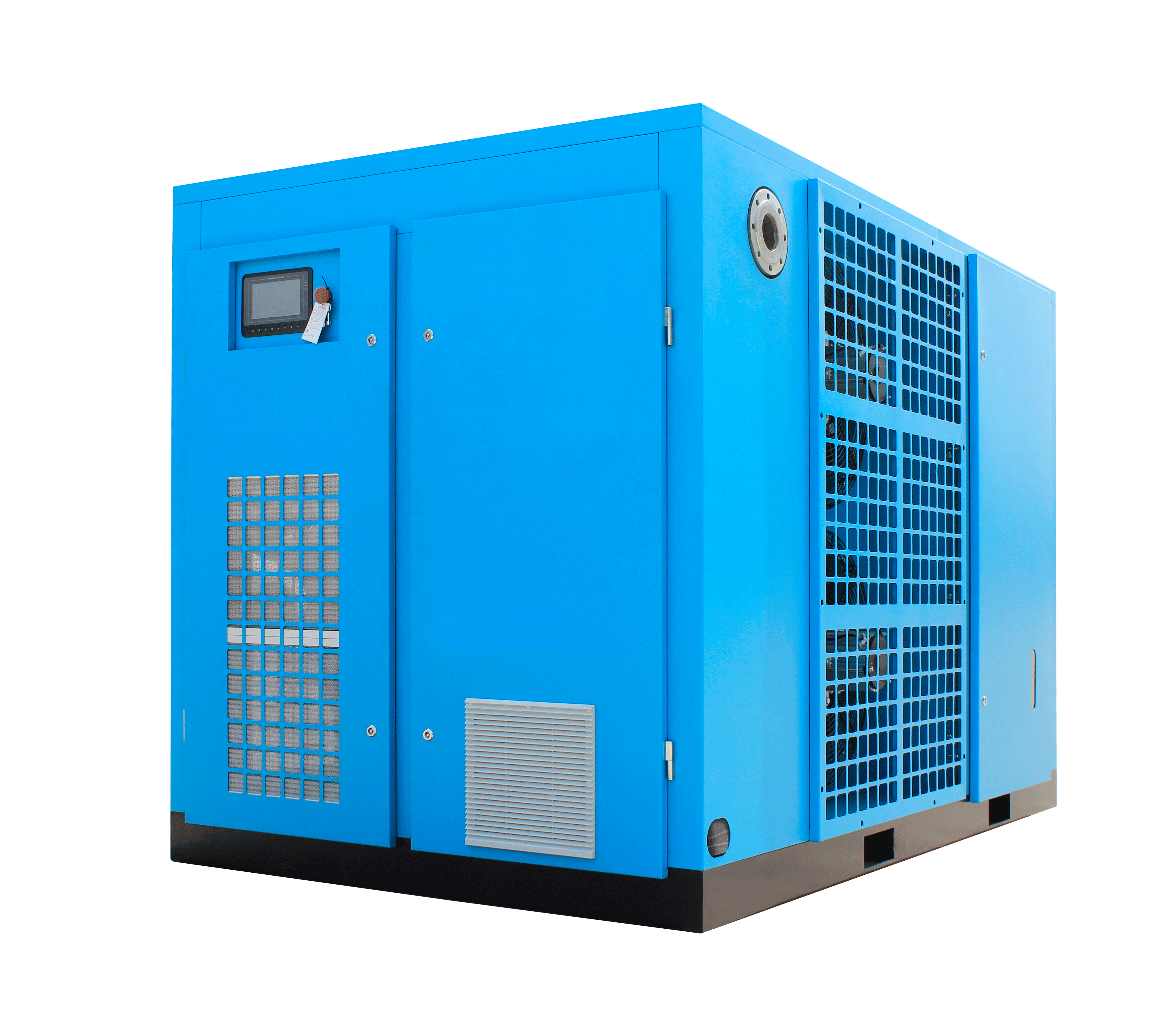
Evaluating output requires precise definitions. You must understand free air delivery (FAD) to succeed. FAD is the actual volume of compressed air delivered to your terminal network. We measure this volume at the compressor outlet. However, we mathematically reference it back to the specific ambient conditions at the machine intake.
Navigating the acronym soup serves as your primary evaluation dimension. You will encounter FAD, ACFM (Actual Cubic Feet per Minute), SCFM (Standard), and Nm³/h (Normal cubic meters per hour). SCFM assumes standard ideal conditions. ACFM measures actual site conditions. FAD measures delivered air adjusted to intake conditions. Nm³/h uses normal atmospheric standards.
This creates a major implementation risk. Unscrupulous vendors might use SCFM or theoretical displacement to artificially inflate their output numbers. You might think you are buying a 500 CFM machine. In reality, it only delivers 420 ACFM on your factory floor.
Site condition variables heavily impact actual performance. Ambient temperature, ambient humidity, and site altitude derate theoretical FAD significantly. Hot air is less dense. Humid air forces the machine to process water vapor instead of usable air. High altitudes offer less intake pressure. You must request vendor quotes based on local site conditions.
Flow Measurement Standards Comparison
| Metric | Full Name | Reference Conditions | Practical Application |
|---|---|---|---|
| FAD | Free Air Delivery | Actual local intake conditions | Best for evaluating actual machine output. |
| ACFM | Actual Cubic Feet per Minute | Actual site conditions (temp, pressure) | Excellent for precise system sizing in North America. |
| SCFM | Standard Cubic Feet per Minute | Standardized (often 68°F, 0% humidity) | Often inflates apparent capacity. Use with caution. |
| Nm³/h | Normal Cubic Meters per Hour | 0°C, 1 atmosphere, 0% humidity | Standard European metric. Requires conversion for field use. |
Rotary screw dynamics dictate an inverse relationship between pressure and volume. When you compress air to a higher pressure, it requires more physical work. If your motor size remains fixed, achieving higher pressure reduces the maximum volume of air processed. You cannot maximize both variables simultaneously without upgrading the motor.
You must differentiate between maximum design limits and optimal plant requirements. The compressor working pressure represents the target output state. The maximum working pressure is just an engineering safety limit. You should never operate at the maximum limit continuously.
Engineers often fall victim to the "artificial demand" risk. They buy higher pressure just in case they need it later. This engineering fallacy carries a massive financial penalty. Higher system pressure pushes air through existing leaks much faster. It exponentially increases energy costs. Remember, every single bar of excess pressure demands 7% more electrical power.
Evaluate your system honestly. Many facilities wrongly compensate for terrible pipe networks. They experience a 2-bar pressure drop across the factory. Instead of increasing pipe diameters, they buy a 10-bar compressor to deliver 8-bar to the tools. This guarantees massive electrical waste.
Many buyers confuse electrical input with usable mechanical work. The compressor motor power (measured in kW or HP) only dictates the electrical draw from your grid. It tells you nothing about the aerodynamic efficiency of the rotary air end. A poor air end design wastes that motor power as heat.
Specific Energy Requirement (SER) serves as the core benchmark for comparison. It measures the exact power consumed per unit of flow. You will typically see this expressed as kW / 100 cfm or kW / m³/min. Lower numbers indicate better efficiency. SER acts as the ultimate truth-teller in vendor proposals.
You need trustworthiness markers when reviewing SER claims. Always demand testing data compliant with ISO 1217 Annex C or Annex E. This globally accepted standard verifies energy claims objectively. It prevents manufacturers from hiding auxiliary fan power or cooling pump power from their efficiency ratings.
Advanced evaluators also look at isentropic efficiency. This compares the theoretical ideal compression energy against the actual consumed energy. It reveals the true engineering quality of the air end. A highly efficient air end requires less motor power to achieve the exact same FAD.
Selecting the right equipment requires a disciplined shortlisting logic. Skipping these steps leads to poor procurement decisions. Follow this exact sequence to evaluate options fairly.
Verification and compliance protect your investment. Demand official data sheets from every vendor. These sheets must explicitly state performance tolerances according to ISO recognized standards. Do not accept "rule of thumb" estimates or marketing brochures. Hold vendors legally accountable to their published data.
Take direct action before finalizing any specification sheet. We strongly recommend initiating a comprehensive air demand audit. Use data-logging equipment on your existing machinery for at least seven days. Capture peak shifts, weekend drops, and lunch breaks. Real data destroys assumptions and guides perfect sizing.
Evaluating industrial air systems requires clarity and discipline. Always remember your core hierarchy: FAD is your target, pressure is your mechanical constraint, and motor power is your electrical cost. Balancing these three variables prevents oversized investments and protects daily operational budgets.
Never accept initial specifications at face value. Demand transparent data. Ensure all proposals reflect your actual site environments rather than ideal factory test labs. Standardize your metrics to reveal the true cost of generating compressed air.
Take the next step toward system optimization today. Contact a certified application engineer to schedule a comprehensive system audit. Utilize a specific power calculator to verify vendor claims before signing any purchase orders.
A: You must use the ideal gas law to adjust actual intake volume to normal conditions. Normal conditions are defined as 0°C (or sometimes 20°C depending on the region), 1 atmosphere of pressure, and 0% relative humidity. You multiply the FAD by temperature and pressure correction factors to find the equivalent Nm³/h.
A: A motor provides a fixed amount of rotational energy. Pushing air to a higher pressure requires more physical work per cubic foot. Because the motor cannot provide more power than its rating, the compressor air end must take in and process a smaller total volume of air to reach that higher pressure.
A: A realistic benchmark for standard 100 psi fixed-speed systems falls between 18 and 22 kW/100 cfm. Advanced two-stage rotary models often achieve 16 to 18 kW/100 cfm. Variable Speed Drive (VSD) models will alter these benchmarks slightly depending on where they operate on their turndown curve.
A: You should base sizing on a comprehensive load profile, not a single data point. We recommend installing a highly efficient base-load fixed-speed unit to handle your continuous average demand. You should then supplement this with a properly sized VSD unit to trim peak fluctuations and handle varying shifts efficiently.


