
- Home
- Products
- Hot
- About Us
- Services
- Industry
- Contact

Views: 0 Author: Site Editor Publish Time: 2026-08-31 Origin: Site


A reliable oil filter acts as the ultimate shield for your compressor airend. It prevents catastrophic mechanical failure and keeps costly facility downtime at bay. However, recognizing an early restriction is crucial for plant managers. An air compressor oil filter blockage does more than just halt contaminant filtration. It actively starves the entire rotary system of vital cooling and fluid flow. Without adequate fluid circulation, internal friction spikes rapidly. The resulting heat can severely damage sensitive rotor profiles. You do not always need to tear down the machine immediately to find a problem. Accurately diagnosing a restriction requires you to evaluate specific performance metrics first. By moving logically from observable gauge symptoms to a hands-on physical inspection, you can protect your equipment effectively. We will explore exactly what signs to monitor and how to respond safely.
Restricted fluid flow creates immediate and severe consequences for your daily operations. A clogged filtration media forces the compressor motor to work significantly harder. The machine must expend extra energy to push thick fluid through blinded paper pores. This physical resistance causes electrical amperage to rise steadily. Energy consumption spikes as a direct result. Furthermore, the airend experiences accelerated mechanical wear. You risk sudden, unexpected production stops when the system inevitably overheats.
Most industrial compressors feature an internal safety mechanism called a bypass valve. Manufacturers design this spring-loaded valve to prevent total oil starvation. If the filter clogs completely, the internal pressure overcomes the spring tension. The valve opens automatically to allow fluid to bypass the media. This action keeps the compressor running, but it introduces a severe secondary risk. The system now circulates highly contaminated, unfiltered oil directly into the sensitive rotors. Dirt, sludge, and metal particulates flow straight into precision bearings. Operating in bypass mode damages the internal components very quickly.
When you initiate a maintenance check, you need clear success criteria. Why are we evaluating this component? The primary goal involves restoring optimal operating temperatures across the machine. You want to return the pressure differentials back to normal baseline levels. A thorough diagnostic also verifies no secondary damage has occurred to the rotary elements. Ultimately, a successful check brings your system back to safe, efficient, and reliable operation.
Common mistakes during early diagnosis include:
The most reliable early warning of trouble is a shift in differential pressure. You must monitor the Delta P gauge across the filter housing regularly. Modern digital controllers display this metric directly on the main screen. Older pneumatic machines use physical analog gauges. As debris builds up inside the pleats, fluid flow slows down noticeably. The pressure before the filter becomes much higher than the pressure exiting it.
You should establish strict warning thresholds for your maintenance team. An oil filter pressure drop exceeding 10 to 15 PSI (0.7 to 1.0 bar) typically indicates a severe restriction. At this specific stage, immediate replacement becomes necessary. Acting quickly prevents the bypass valve from activating and circulating dirty fluid.
Proper system cooling relies entirely on steady fluid circulation. Poor compressor lubrication directly causes poor heat dissipation. The twin rotors generate intense friction and heat during standard air compression. The circulating fluid normally absorbs this heat and carries it to the cooler. If you notice unexpected temperature spikes under heavy loads, check your filtration circuit first. Elevated discharge temperatures often point directly back to a restricted fluid path.
Your ears also provide excellent diagnostic feedback. Listen closely to the machine during peak operation cycles. Chattering or high-pitched whining noises indicate dangerous metal-to-metal contact. This distinct mechanical sound means the airend bearings are starving for fluid. You must execute an immediate emergency shutdown if you hear these noises. Ignoring auditory warnings guarantees catastrophic internal failure.
Diagnostic Symptom Reference Matrix
| Observable Symptom | Probable Cause | Recommended Action |
|---|---|---|
| Delta P exceeds 15 PSI | Media fully blinded by sludge or dust | Shut down and replace element immediately. |
| Discharge temp hits 220°F+ | Reduced fluid flow preventing heat transfer | Check thermostatic valve and filter restriction. |
| High-pitched whining noise | Rotor or bearing starvation | Execute emergency stop. Inspect bearings. |
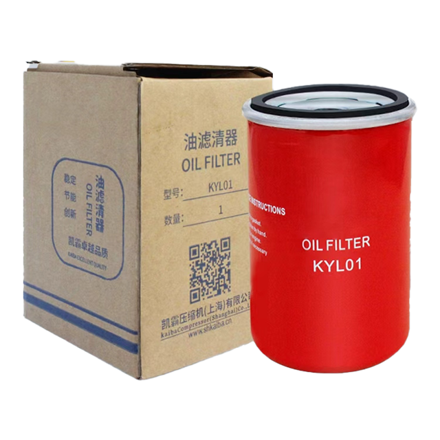
Safety remains the absolute pre-requisite before any physical intervention. You must power down the compressor completely at the main breaker. Isolate the unit using standard lockout/tagout (LOTO) procedures. You must also fully depressurize the system before touching any pressurized components. Open the blow-down valve manually to drain residual air from the sump tank. Removing a housing while under pressure causes severe injuries and fatal accidents.
Once you verify a zero-energy state, begin the physical removal process. Use a properly sized strap wrench to remove spin-on style cartridges. Secure the wrench near the base of the canister, not the top. This prevents the thin metal casing from crushing. If you have a bolt-on housing, unbolt the cover carefully. Apply even pressure during removal to avoid costly thread damage.
Now, proceed with the actual filter element inspection under bright lighting. Examine the paper pleats closely. You are looking for several specific failure indicators. Watch for heavy sludge buildup coating the entire surface. Look for collapsed, torn, or visibly warped media pleats. These structural failures happen when the differential pressure climbs too high.
The type of debris you find tells a distinct mechanical story. Normal airborne dirt indicates standard environmental wear over time. However, metallic flakes require immediate and urgent attention. Finding brass or steel shavings in the media reveals a larger airend bearing issue. Simply changing the part will not solve this root problem. You will need a comprehensive mechanical diagnostic to save the compressor from total destruction.
Factory manuals often recommend a standard 2,000-hour or 4,000-hour maintenance interval. Keep in mind, these numbers rely entirely on assumptions of ideal, clean conditions. Equipment manufacturers assume your machine sits in a climate-controlled, dust-free compressor room. Many facilities operate in far harsher realities. Sticking blindly to a calendar date can lead to sudden machine failures.
Your specific plant environment dictates true media lifespan. Dusty, humid, or high-particulate air drastically reduces the viability of the paper pleats. Cement plants, paper mills, and woodworking shops overload filtration systems rapidly. The inlet air filter catches large particles, but microscopic dust still enters the fluid stream. You must adjust your schedule to match your ambient air quality. In severe environments, operators often cut the factory schedule in half.
Fluid quality matters just as much as ambient air quality. Mixing incompatible synthetic and mineral fluids represents a major industry mistake. This chemical clash creates a thick gel that rapidly coats internal components. Running the machine constantly above recommended temperatures accelerates this thermal degradation. The degraded fluid turns into a sticky varnish. This varnish prematurely blinds the microscopic pores of the filter paper. Once varnish forms, regular changes alone will not fix the issue. You must chemically flush the entire fluid circuit to restore normal flow.
Best practices for interval management include:
Some technicians attempt to wash and reuse old elements to save money. This practice represents a dangerous operational myth. You should never wash modern filtration media. Industrial solvents aggressively degrade the synthetic and cellulose binders holding the paper together. Washing the material ruins the specific micron rating completely. The paper might look clean, but it will now pass large, damaging particles. Furthermore, you risk introducing harsh cleaning chemicals directly into the main fluid supply. These chemicals break down fluid viscosity rapidly.
Always choose full replacement over attempted cleaning. When selecting a new part, you must evaluate specific technical criteria carefully. The market offers both OEM and aftermarket options. Matching the external thread size alone is a dangerous mistake. You must verify the specific micron rating matches the original factory design. Confirm the bypass valve cracking pressure aligns perfectly with system specifications. If an aftermarket unit has a lower cracking pressure, it will bypass constantly. Finally, ensure the rubber gasket material offers full chemical compatibility with your specific synthetic fluid.
After selecting the correct replacement part, follow a clear installation path. First, document the old unit's physical condition in your maintenance log. If you spot severe varnish during inspection, execute a full system flush before proceeding. Next, lubricate the new rubber gasket with a light coat of clean fluid. This prevents the gasket from bunching or tearing during tightening. Install the new canister securely by hand. Never use a wrench to tighten a spin-on canister. Finally, turn the machine on, check for leaks, and reset the maintenance timer on your controller.
Key replacement evaluation factors:
Diagnosing a restriction requires a methodical approach and attention to detail. You must monitor differential pressure drops carefully during daily rounds. Observing temperature trends helps catch thermal issues before they escalate. Finally, conducting a safe, thorough physical inspection confirms the exact condition of the media. Following these steps ensures you catch flow restrictions early.
Facility managers and maintenance technicians should always act proactively. Schedule replacements long before the internal bypass valve opens. Never wait for late-stage failure symptoms, such as high-pitched whining, to appear. Consult your specific OEM manual today to identify your exact pressure tolerances. Taking preventive action protects your airend, preserves your warranty, and ensures continuous facility production.
A: Yes. Most industrial compressors feature internal thermal shut-off switches. If a severe restriction starves the airend of fluid, internal friction rises quickly. The system overheats rapidly under heavy load. Once temperatures exceed safety limits, these sensors trip automatically. This failsafe mechanism shuts the machine down to prevent catastrophic rotor damage.
A: You should perform daily visual checks of the Delta P gauge and temperature display. Watch for any unusual spikes. For physical inspections or replacements, rely on your specific environment's adjusted schedule. Dirty or dusty facilities require much more frequent checks than a standard factory baseline suggests.
A: The oil filter cleans liquid fluid before it enters the airend for cooling and lubrication. It captures solid particulates, dirt, and sludge. Conversely, the air/oil separator removes residual fluid mist from the compressed air stream. It ensures the final air exiting into your plant remains clean and oil-free.


